
This is the fourth tutorial in our Android series. In this lesson, we’re going to add to what we learned in lesson three and learn how to add texturing.We’ll look at how to read an image from the application resources, load this image into OpenGL ES, and display it on the screen.
Follow along with me and you’ll understand basic texturing in no time flat!
Assumptions and prerequisites
Each lesson in this series builds on the lesson before it. This lesson is an extension of lesson three, so please be sure to review that lesson before continuing on. Here are the previous lessons in the series:
- Android Lesson One: Getting Started
- Android Lesson Two: Ambient and Diffuse Lighting
- Android Lesson Three: Moving to Per-Fragment Lighting
The basics of texturing
The art of texture mapping (along with lighting) is one of the most important parts of building up a realistic-looking 3D world. Without texture mapping, everything is smoothly shaded and looks quite artificial, like an old console game from the 90s.
The first games to start heavily using textures, such as Doom and Duke Nukem 3D, were able to greatly enhance the realism of the gameplay through the added visual impact — these were games that could start to truly scare us if played at night in the dark.
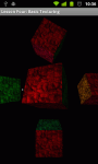
Here’s a look at a scene, without and with texturing:
|
|
|
In the image on the left, the scene is lit with per-pixel lighting and colored. Otherwise the scene appears very smooth. There are not many places in real-life where we would walk into a room full of smooth-shaded objects like this cube.In the image on the right, the same scene has now also been textured. The ambient lighting has also been increased because the use of textures darkens the overall scene, so this was done so you could also see the effects of texturing on the side cubes. The cubes have the same number of polygons as before, but they appear a lot more detailed with the new texture. For those who are curious, the texture source is from public domain textures. |


Texture coordinates
In OpenGL, texture coordinates are sometimes referred to in coordinates (s, t) instead of (x, y). (s, t) represents a texel on the texture, which is then mapped to the polygon. Another thing to note is that these texture coordinates are like other OpenGL coordinates: The t (or y) axis is pointing upwards, so that values get higher the higher you go.
In most computer images, the y axis is pointing downwards. This means that the top-left most corner of the image is (0, 0), and the y values increase the lower you go.In other words, the y-axis is flipped between OpenGL’s coordinate system and most computer images, and this is something you need to take into account.

The basics of texture mapping
In this lesson, we will look at regular 2D textures (GL_TEXTURE_2D) with red, green, and blue color information (GL_RGB). OpenGL ES also offers other texture modes that let you do different and more specialized effects. We’ll look at point sampling using GL_NEAREST. GL_LINEAR and mip-mapping will be covered in a future lesson.
Let’s start getting into the code and see how to start using basic texturing in Android!
Vertex shader
We’re going to take our per-pixel lighting shader from the previous lesson, and add texturing support. Here are the new changes:
attribute vec2 a_TexCoordinate; // Per-vertex texture coordinate information we will pass in.

...

varying vec2 v_TexCoordinate;   // This will be passed into the fragment shader.

...
// Pass through the texture coordinate.
v_TexCoordinate = a_TexCoordinate;
In the vertex shader, we add a new attribute of type vec2 (an array with two components) that will take in texture coordinate information as input. This will be per-vertex, like the position, color, and normal data. We also add a new varying that will pass this data through to the fragment shader via linear interpolation across the surface of the triangle.
Fragment shader
uniform sampler2D u_Texture;    // The input texture.

...

varying vec2 v_TexCoordinate; // Interpolated texture coordinate per fragment.

...

// Add attenuation.
 diffuse = diffuse * (1.0 / (1.0 + (0.10 * distance)));

...

// Add ambient lighting
 diffuse = diffuse + 0.3;

...

// Multiply the color by the diffuse illumination level and texture value to get final output color.

gl_FragColor = (v_Color * diffuse * texture2D(u_Texture, v_TexCoordinate));
We add a new uniform of type sampler2D to represent the actual texture data (as opposed to texture coordinates). The varying passes in the interpolated texture coordinates from the vertex shader, and we call texture2D(texture, textureCoordinate) to read in the value of the texture at the current coordinate. We then take this value and multiply it with the other terms to get the final output color.
Adding in a texture this way darkens the overall scene somewhat, so we also boost up the ambient lighting a bit and reduce the lighting attenuation.
Loading in the texture from an image file
	public static int loadTexture(final Context context, final int resourceId)
	{
		final int[] textureHandle = new int[1];

		GLES20.glGenTextures(1, textureHandle, 0);

		if (textureHandle[0] != 0)
		{
			final BitmapFactory.Options options = new BitmapFactory.Options();
			options.inScaled = false;	// No pre-scaling

			// Read in the resource
			final Bitmap bitmap = BitmapFactory.decodeResource(context.getResources(), resourceId, options);

			// Bind to the texture in OpenGL
			GLES20.glBindTexture(GLES20.GL_TEXTURE_2D, textureHandle[0]);

			// Set filtering
			GLES20.glTexParameteri(GLES20.GL_TEXTURE_2D, GLES20.GL_TEXTURE_MIN_FILTER, GLES20.GL_NEAREST);
			GLES20.glTexParameteri(GLES20.GL_TEXTURE_2D, GLES20.GL_TEXTURE_MAG_FILTER, GLES20.GL_NEAREST);

			// Load the bitmap into the bound texture.
			GLUtils.texImage2D(GLES20.GL_TEXTURE_2D, 0, bitmap, 0);

			// Recycle the bitmap, since its data has been loaded into OpenGL.
			bitmap.recycle();
		}

		if (textureHandle[0] == 0)
		{
			throw new RuntimeException("Error loading texture.");
		}

		return textureHandle[0];
	}
This bit of code will read in a graphics file from your Android res folder and load it into OpenGL. I’ll explain what each part does.
We first need to ask OpenGL to create a new handle for us. This handle serves as a unique identifier, and we use it whenever we want to refer to the same texture in OpenGL.
final int[] textureHandle = new int[1];
GLES20.glGenTextures(1, textureHandle, 0);
The OpenGL method can be used to generate multiple handles at the same time; here we generate just one.
Once we have a texture handle, we use it to load the texture. First, we need to get the texture in a format that OpenGL will understand. We can’t just feed it raw data from a PNG or JPG, because it won’t understand that. The first step that we need to do is to decode the image file into an Android Bitmap object:
final BitmapFactory.Options options = new BitmapFactory.Options();
options.inScaled = false;	// No pre-scaling

// Read in the resource
final Bitmap bitmap = BitmapFactory.decodeResource(context.getResources(), resourceId, options);
By default, Android applies pre-scaling to bitmaps depending on the resolution of your device and which resource folder you placed the image in. We don’t want Android to scale our bitmap at all, so to be sure, we set inScaled to false.
// Bind to the texture in OpenGL
GLES20.glBindTexture(GLES20.GL_TEXTURE_2D, textureHandle[0]);

// Set filtering
GLES20.glTexParameteri(GLES20.GL_TEXTURE_2D, GLES20.GL_TEXTURE_MIN_FILTER, GLES20.GL_NEAREST);
GLES20.glTexParameteri(GLES20.GL_TEXTURE_2D, GLES20.GL_TEXTURE_MAG_FILTER, GLES20.GL_NEAREST);
We then bind to the texture and set a couple of parameters. Binding to a texture tells OpenGL that subsequent OpenGL calls should affect this texture. We set the default filters to GL_NEAREST, which is the quickest and also the roughest form of filtering. All it does is pick the nearest texel at each point in the screen, which can lead to graphical artifacts and aliasing.
- GL_TEXTURE_MIN_FILTER — This tells OpenGL what type of filtering to apply when drawing the texture smaller than the original size in pixels.
- GL_TEXTURE_MAG_FILTER — This tells OpenGL what type of filtering to apply when magnifying the texture beyond its original size in pixels.
// Load the bitmap into the bound texture.
GLUtils.texImage2D(GLES20.GL_TEXTURE_2D, 0, bitmap, 0);

// Recycle the bitmap, since its data has been loaded into OpenGL.
bitmap.recycle();
Android has a very useful utility to load bitmaps directly into OpenGL. Once you’ve read in a resource into a Bitmap object, GLUtils.texImage2D() will take care of the rest. Here’s the method signature:
public static void texImage2D (int target, int level, Bitmap bitmap, int border)
We want a regular 2D bitmap, so we pass in GL_TEXTURE_2D as the first parameter. The second parameter is for mip-mapping, and lets you specify the image to use at each level. We’re not using mip-mapping here so we’ll put 0 which is the default level. We pass in the bitmap, and we’re not using the border so we pass in 0.
We then call recycle() on the original bitmap, which is an important step to free up memory. The texture has been loaded into OpenGL, so we don’t need to keep a copy of it lying around. Yes, Android apps run under a Dalvik VM that performs garbage collection, but Bitmap objects contain data that resides in native memory and they take a few cycles to be garbage collected if you don’t recycle them explicitly. This means that you could actually crash with an out of memory error if you forget to do this, even if you no longer hold any references to the bitmap.
Applying the texture to our scene
First, we need to add various members to the class to hold stuff we need for our texture:
/** Store our model data in a float buffer. */
private final FloatBuffer mCubeTextureCoordinates;

/** This will be used to pass in the texture. */
private int mTextureUniformHandle;

/** This will be used to pass in model texture coordinate information. */
private int mTextureCoordinateHandle;

/** Size of the texture coordinate data in elements. */
private final int mTextureCoordinateDataSize = 2;

/** This is a handle to our texture data. */
private int mTextureDataHandle;
We basically need to add new members to track what we added to the shaders, as well as hold a reference to our texture.
Defining the texture coordinates
We define our texture coordinates in the constructor:
// S, T (or X, Y)
// Texture coordinate data.
// Because images have a Y axis pointing downward (values increase as you move down the image) while
// OpenGL has a Y axis pointing upward, we adjust for that here by flipping the Y axis.
// What's more is that the texture coordinates are the same for every face.
final float[] cubeTextureCoordinateData =
{
		// Front face
		0.0f, 0.0f,
		0.0f, 1.0f,
		1.0f, 0.0f,
		0.0f, 1.0f,
		1.0f, 1.0f,
		1.0f, 0.0f,

...
The coordinate data might look a little confusing here. If you go back and look at how the position points are defined in Lesson 3, you’ll see that we define two triangles per face of the cube. The points are defined like this:
(Triangle 1)
Upper-left,
Lower-left,
Upper-right,
(Triangle 2)
Lower-left,
Lower-right,
Upper-right
The texture coordinates are pretty much the position coordinates for the front face, but with the Y axis flipped to compensate for the fact that in graphics images, the Y axis points in the opposite direction of OpenGL’s Y axis.
Setting up the texture
We load the texture in the onSurfaceCreated() method.
@Override
public void onSurfaceCreated(GL10 glUnused, EGLConfig config)
{

	...

	// The below glEnable() call is a holdover from OpenGL ES 1, and is not needed in OpenGL ES 2.
	// Enable texture mapping
	// GLES20.glEnable(GLES20.GL_TEXTURE_2D);

	...

	mProgramHandle = ShaderHelper.createAndLinkProgram(vertexShaderHandle, fragmentShaderHandle,
			new String[] {"a_Position",  "a_Color", "a_Normal", "a_TexCoordinate"});

	...

	// Load the texture
	mTextureDataHandle = TextureHelper.loadTexture(mActivityContext, R.drawable.bumpy_bricks_public_domain);
We pass in “a_TexCoordinate” as a new attribute to bind to in our shader program, and we load in our texture using the loadTexture() method we created above.
Using the texture
We also add some code to the onDrawFrame(GL10 glUnused) method.
@Override
public void onDrawFrame(GL10 glUnused)
{

	...

	mTextureUniformHandle = GLES20.glGetUniformLocation(mProgramHandle, "u_Texture");
	mTextureCoordinateHandle = GLES20.glGetAttribLocation(mProgramHandle, "a_TexCoordinate");

	// Set the active texture unit to texture unit 0.
	GLES20.glActiveTexture(GLES20.GL_TEXTURE0);

	// Bind the texture to this unit.
	GLES20.glBindTexture(GLES20.GL_TEXTURE_2D, mTextureDataHandle);

	// Tell the texture uniform sampler to use this texture in the shader by binding to texture unit 0.
	GLES20.glUniform1i(mTextureUniformHandle, 0);
We get the shader locations for the texture data and texture coordinates. In OpenGL, textures need to be bound to texture units before they can be used in rendering. A texture unit is what reads in the texture and actually passes it through the shader so it can be displayed on the screen. Different graphics chips have a different number of texture units, so you’ll need to check if additional texture units exist before using them.
First, we tell OpenGL that we want to set the active texture unit to the first unit, texture unit 0. Our call to glBindTexture() will then automatically bind the texture to the first texture unit. Finally, we tell OpenGL that we want to bind the first texture unit to the mTextureUniformHandle, which refers to “u_Texture” in the fragment shader.
In short:
- Set the active texture unit.
- Bind a texture to this unit.
- Assign this unit to a texture uniform in the fragment shader.
Repeat for as many textures as you need.
Further exercises
Once you’ve made it this far, you’re done! Surely that wasn’t as bad as you expected… or was it? 😉 As your next exercise, try to add multi-texturing by loading in another texture, binding it to another unit, and using it in the shader.
Review
Here is a review of the full shader code, as well as a new helper function that we added to read in the shader code from the resource folder instead of storing it as a Java String:
Vertex shader
uniform mat4 u_MVPMatrix;		// A constant representing the combined model/view/projection matrix.
uniform mat4 u_MVMatrix;		// A constant representing the combined model/view matrix.

attribute vec4 a_Position;		// Per-vertex position information we will pass in.
attribute vec4 a_Color;			// Per-vertex color information we will pass in.
attribute vec3 a_Normal;		// Per-vertex normal information we will pass in.
attribute vec2 a_TexCoordinate; // Per-vertex texture coordinate information we will pass in.

varying vec3 v_Position;		// This will be passed into the fragment shader.
varying vec4 v_Color;			// This will be passed into the fragment shader.
varying vec3 v_Normal;			// This will be passed into the fragment shader.
varying vec2 v_TexCoordinate;   // This will be passed into the fragment shader.

// The entry point for our vertex shader.
void main()
{
	// Transform the vertex into eye space.
	v_Position = vec3(u_MVMatrix * a_Position);

	// Pass through the color.
	v_Color = a_Color;

	// Pass through the texture coordinate.
	v_TexCoordinate = a_TexCoordinate;

	// Transform the normal's orientation into eye space.
    v_Normal = vec3(u_MVMatrix * vec4(a_Normal, 0.0));

	// gl_Position is a special variable used to store the final position.
	// Multiply the vertex by the matrix to get the final point in normalized screen coordinates.
	gl_Position = u_MVPMatrix * a_Position;
}
Fragment shader
precision mediump float;       	// Set the default precision to medium. We don't need as high of a
								// precision in the fragment shader.
uniform vec3 u_LightPos;       	// The position of the light in eye space.
uniform sampler2D u_Texture;    // The input texture.

varying vec3 v_Position;		// Interpolated position for this fragment.
varying vec4 v_Color;          	// This is the color from the vertex shader interpolated across the
  								// triangle per fragment.
varying vec3 v_Normal;         	// Interpolated normal for this fragment.
varying vec2 v_TexCoordinate;   // Interpolated texture coordinate per fragment.

// The entry point for our fragment shader.
void main()
{
	// Will be used for attenuation.
    float distance = length(u_LightPos - v_Position);

	// Get a lighting direction vector from the light to the vertex.
    vec3 lightVector = normalize(u_LightPos - v_Position);

	// Calculate the dot product of the light vector and vertex normal. If the normal and light vector are
	// pointing in the same direction then it will get max illumination.
    float diffuse = max(dot(v_Normal, lightVector), 0.0);

	// Add attenuation.
    diffuse = diffuse * (1.0 / (1.0 + (0.10 * distance)));

    // Add ambient lighting
    diffuse = diffuse + 0.3;

	// Multiply the color by the diffuse illumination level and texture value to get final output color.
    gl_FragColor = (v_Color * diffuse * texture2D(u_Texture, v_TexCoordinate));
  }
How to read in the shader from a text file in the raw resources folder
public static String readTextFileFromRawResource(final Context context,
			final int resourceId)
	{
		final InputStream inputStream = context.getResources().openRawResource(
				resourceId);
		final InputStreamReader inputStreamReader = new InputStreamReader(
				inputStream);
		final BufferedReader bufferedReader = new BufferedReader(
				inputStreamReader);

		String nextLine;
		final StringBuilder body = new StringBuilder();

		try
		{
			while ((nextLine = bufferedReader.readLine()) != null)
			{
				body.append(nextLine);
				body.append('\n');
			}
		}
		catch (IOException e)
		{
			return null;
		}

		return body.toString();
	}
Wrapping up
The full source code for this lesson can be downloaded from the project site on GitHub.
As always, please don’t hesitate to leave feedbacks or comments, and thanks for stopping by!

About the book
Android is booming like never before, with millions of devices shipping every day. In OpenGL ES 2 for Android: A Quick-Start Guide, you’ll learn all about shaders and the OpenGL pipeline, and discover the power of OpenGL ES 2.0, which is much more feature-rich than its predecessor.
It’s never been a better time to learn how to create your own 3D games and live wallpapers. If you can program in Java and you have a creative vision that you’d like to share with the world, then this is the book for you.

Thank you for this new lesson. Now if you have the possibility to explain how to create shadows using opengl ES 2, you will fit all my needs… for now 😉
Thanks again
Hmm… probably won’t make the first 10 lessons as that is a more advanced topic but you never know!
Thank you very much. there is a spell error in this tutorial-“Here’s a look at a scene, without and without texturing:” should be “with and without texturing:”
Thanks for letting me know, I’ve just fixed it!
Hi! These tutorials helped me so much! Any chance you’d do a Bump Mapping one? Thanks! dc
Yes, the tutorials won’t be complete without covering bump mapping!
Very good tutorial. Clear, useful and polished like few others on the web.
It just took me some time to run the source code (I had to create a new project, copy the file in and configure the XMLs). I have a question about the textures coordinates. Looking at the code, I see that the texture coordinate (0,0) is assigned to the top left corner of the square, (0,1) to the bottom left and (1,1) to the top right. Basically the picture of the “OpenGl’s Texture Coordinate System should have (0,0) on the top left. And the comment in the code “Because images have a Y axis pointing downward (values increase as you move down the image) while OpenGL has a Y axis pointing upward” suggests the same thing. Is there an error in that picture or am I missing something? Thank you
This is a good point. The image represents OpenGl’s texture coordinate system. As you can see, Y values increase as they go upwards. However, in our computer image, Y values increase as they go downwards. If we do nothing, our image will appear upside down.
So, we have two options. The first is that we can flip the bitmap when we read it in, which is what I’ve seen some other tutorials do. This is more expensive since we have to manipulate the image data before loading it into OpenGL. The second alternative is that we can simply flip the texture coordinates, and that is what we do here.
We could also do many more effects by manipulating these texture coordinates. We could scale the texture, shear it, or have it pan across the surface of the cube.
P.S. Regarding the project do you mean the source at https://github.com/learnopengles/Learn-OpenGLES-Tutorials/tree/master/android/AndroidOpenGLESLessons ? There should be an eclipse project there but I haven’t tried importing it from scratch to be honest.
Thanks for the great comment!
Thank you for your answer!
Yes, I took the project from github. I imported it in Eclipse, but it didn’t run because of some missing references, in particular the Libraries in the Java Build Path options. It should be probably possible to configure it quickly, but I have not much experience with Eclipse and the Android SDK, so I just created a new project. I also had to remove the @override statement from some methods because it looks like the compiler doesn’t like them if the class is implementing such method of an interface, instead of actually overriding an existing method of a concrete super class. I’m using Eclipse 3.7.1 with the Android SDK r16, and I compile in Android 2.3 and execute on my HTC Desire S.
From you answer I think I got what I was missing. I was seeing OpenGL ES and the Android framework as a whole, while the former sits on top of the latter. So I suppose that OpenGL ES requires the underlying platform to implement a sort of
Color image.getPixel(int i, int j)
and then it uses it to sample the texel by doing
texelColor = image.getPixel( floor(currentS * image.width), floor(currentT * image.height) );
with currentS and currentT floats in [0,1]
So basically OpenGL’s texture coordinates are just values used to find the indices i and j to get the pixels from the image.
What makes the difference is the implementation of the method getPixel(…), because on a platform image.getPixel(0,0) could be the bottom left pixel (as it was probably on the original platform underlying the original OpenGL library), on another it could be the the top left (as it is for the android.graphics.Bitmap class in the Android framework).
But I’m just guessing.
Thank you again for the answers and the great tutorials!
I’ll have to try the project out and see what’s happening! It’s very possible there’s a hardcoded path or more in there somewhere. You can also fix the @Override issue by setting your java compiler compliance level to 1.6 instead of 1.5. There was a change in the language that allows the @Override for interfaces.
Actually getPixel(0,0) will return the same pixel from a texture in both cases, but you’re on the right track. It’s more about the coordinate system that the screen uses. I admit that this is a confusing issue and I have confused myself more than once on this. 🙂 Basically, Android’s graphics layer will see the top-left corner as (0,0), and the bottom-right as (480,800) or something like that. In OpenGL, the Y axis is reversed and the coordinates are a bit different: Top-left is (-1, 1), center is (0,0), and bottom-right is (1, -1).
If you want to think about it another way, OpenGL matches the Cartesian system that you used when drawing graphs in school, and it’s the native graphics libraries that have an inverted Y axis.
If we just assigned our texture coordinates to match OpenGL’s coordinates, and our camera was not upside down, then it would be the image that appeared upside down. Why? When it finally draws the image, getPixel(x,y) will still map to the same values (well, OpenGL normalizes the range to [0,1], but 0,0 and maxX, maxY will still map to the same points) but the direction in which they will be drawn will be reversed.
The good thing is that we can transform our coordinates in OpenGL, and we can make up our own texture coordinates, so this is actually a non-issue. If we want to flip our textures, we can just invert the texture coordinates. If we want to do 2D drawing, we can even setup an orthographic projection and make it so that the top-left is (0,0) and the bottom right is (480, 800).
Let me know if this helps out. 🙂
It’s true, I was compiling at level 1.5, I am still new to Java 🙂
Honestly the orientation issue is still not entirely clear to me, but I think there is also some misunderstanding.
I understand the OpenGl WORLD coordinates are Cartesian, this means that X goes positive right, Y goes positive up, and Z goes positive out of the screen (towards our nose!). Right hand rule. OpenGl TEXTURE coordinates should be the same, X goes positive right, Y goes positive up. Like your graph, an like the OpenGL official document http://www.khronos.org/registry/gles/specs/2.0/es_full_spec_2.0.25.pdf page 70.
The winding is counter-clock wise, right hand rule again. According to the document and your example, the texture coordinates are between 0.0 and 1.0.
I get the first three vertices of your code, the vertices of the front face of the cube. These are WORLD coordinates:
-1.0f, 1.0f, 1.0f, (top left)
-1.0f, -1.0f, 1.0f, (bottom left)
1.0f, 1.0f, 1.0f, (top right)
this is a triangle specified in counter-clock wise winding, its normal runs along the positive Z axis, thus it is visible.
The we have to assign the TEXTURE coordinates. Following the OpenGL specification, with the Y axis up, I would expect to set:
0.0, 1.0, (top left)
0.0, 0.0, (bottom left)
1.0, 1.0 (top right)
Instead in the code example the coordinates are
0.0f, 0.0f, (top left)
0.0f, 1.0f, (bottom left)
1.0f, 0.0f, (top right)
which is a system with the Y axis positive downwards.
I modified the texture labelling the corners, and the texture is drawn entirely, and in the correct orientation. This make me deduce that OpenGL TEXTURE (not world) coordinates system has the Y positive downwards.
But the graph in this page and the OpenGL document says that the Y is positive upwards. Then or the graphs are wrong and the TEXTURE coordinate system of OpenGL has the Y positive downwards, or my reasoning above is wrong. Probably the second one, but I can’t prove it.
Sorry to hassle you with this issue, it’s just that I try to fully understand things, and I use to delve into until there are no contradictions.
Hi Ricardo,
I was just wondering if it seemed any clearer with more experimentation or not. 🙂 I feel like I should address this topic specifically in a future tutorial.
Thanks!
Hi,
Is there any special requirement for a particular jpg texture file to be usable?
I select one from the link given http://2.bp.blogspot.com/_Ql_VVzn3j9g/R9kYezpPrnI/AAAAAAAAAcw/c8g7Je0YEyQ/s1600-h/461223193.jpg
However, it shows black color. An entire black screen with a white dot circling around.
If I used the texture file u used in your example, bumpy bricks, it works well.
Any advise?
Thanks.
Hi Alvin,
One primary requirement is that the texture file should be a power of 2. I.e. 256×256, or 512×512. 256×512 should also work. 384×384, etc… would not work, unless the graphics card had specific support for it.
That image is 750×750; please try resizing to 512×512 and let me know if it works then.
Thanks!
These tutorials are fantastic, thank you. I may be missing something, but how do you selectively apply textures to some things and not others? e.g. if you wanted one of your cubes textured and the others smooth, or one textured with bumpy bricks and the others with something else?
Hi Chris,
To switch textures, you would need to keep around several texture data handles. In our example we use “mTextureDataHandle”, so you’d first want to load several different textures into mTextureDataHandleBricks, mTextureDataHandleSomethingElse, etc…
Then, we pass in the right texture just before drawing:
// Bind the texture to this unit.
GLES20.glBindTexture(GLES20.GL_TEXTURE_2D, mTextureDataHandleBricks);
or
GLES20.glBindTexture(GLES20.GL_TEXTURE_2D, mTextureDataHandleSomethingElse);
etc…
To handle the case where some cubes should not be textured, I think you want to use two shaders. You draw textured cubes with the textured shader, and the smooth cubes with the shaders we were using in lesson 3 or lesson 2.
Let me know if this helps. 🙂
OK Yeah, I think that does help a lot. Unfortunately I can’t test it until Monday, but as I understand it, to get smooth and textured shapes, I need to:
1) Create a second set of vertex and fragment shaders (mVertexShader and mVertexTexturedShader, etc)
2) Create a second program handle (one using textured vertex and fragment shader, one not)
3) Add some lines to the “Set program handles” part of onDrawFrame() to define textured program handles vs. non-textured
4) GLES20.glUseProgram(mPerVertexTexturedProgramHandle) vs. mPerVertexProgramHandle ???
5) Make sure I’m using the right program handles when drawing my shapes
And to add a second texture, I can:
1) Either make a second mTextureDataHandle, as you said, or
2) Make mTextureDataHandle an array to store several textures, then
3) Set each subsequent active texture – glActiveTexture(GLES20.GL_TEXTURE[0/1/2/…])
3) GLES20.glBindTexture for each texture defined
Will this allocate each subsequent texture to a different GL_TEXTUREx , so before I draw a shape I can set glActiveTexture to whichever texture I want to use at the time?
I’m sorry for the long comment, just trying to clear it up as much as possible before I actually try running it on Monday. Thanks again for this tutorial.
Hi Chris,
Everything looks good, except there’s no need to switch the glActiveTexture unless you plan to do multi-texturing: rendering multiple textures at the same time. So, you should only need to use GL_TEXTURE0 each time. You’ll only need to switch this line:
// Bind the texture to this unit.
GLES20.glBindTexture(GLES20.GL_TEXTURE_2D, mTextureDataHandle);
Yeah, but suppose I want to use texturing to represent simple text – I would bind each graphic representing a letter or number onto a different ActiveTexture, and when it comes time to draw, select whichever ActiveTexture I want and set that onto the surface texture, yes? There may be more efficient ways to do it, and GL ES only supports up to 30 textures, but if all I need are 10 numbers and a couple of letters, but need them frequently, it would be better to load each of them once and use them as often as necessary rather than unbind and rebind a new image every time.
I’m getting some fairly weird stuff now. Here’s how I set up the texture handles:
// Load the texture
mTextureDataHandle[0] = TextureHelper.loadTexture(mActivityContext, R.drawable.bumpy_bricks_public_domain);
mTextureDataHandle[1] = TextureHelper.loadTexture(mActivityContext, R.drawable.park);
mTextureDataHandle[2] = TextureHelper.loadTexture(mActivityContext, R.drawable.neutral);
// Set the active texture unit to texture unit 0 and bind to the texture data.
GLES20.glActiveTexture(GLES20.GL_TEXTURE1);
GLES20.glBindTexture(GLES20.GL_TEXTURE_2D, mTextureDataHandle[0]);
GLES20.glActiveTexture(GLES20.GL_TEXTURE2);
GLES20.glBindTexture(GLES20.GL_TEXTURE_2D, mTextureDataHandle[1]);
GLES20.glActiveTexture(GLES20.GL_TEXTURE3);
GLES20.glBindTexture(GLES20.GL_TEXTURE_2D, mTextureDataHandle[2]);
and to use them:
GLES20.glUseProgram(mPerVertexTexturedProgramHandle);
GLES20.glUniform1f(mTextureUniformHandle, 2);
drawStuff(…);
GLES20.glUseProgram(mPerVertexProgramHandle);
GLES20.glUseProgram(mPerVertexTexturedProgramHandle);
//Select the proper texture to use
GLES20.glUniform1f(mTextureUniformHandle, 3);
drawQuad();
//Switch back to smooth shader
GLES20.glUseProgram(mPerVertexProgramHandle);
When I run this, both shapes are given the ‘neutral’ texture. If I change which active textures are used at bind time to 0, 1 and 2 then both shapes get the ‘bumpy_bricks’ texture. Any ideas why this might be happening?
I got it working, as outlined above, but when I try to use a .png instead of a .jpg, it doesn’t render. I’m assuming it’s something to do with the way OpenGL ES decodes bitmap vs. vectored images, do you know how that works?
PNG versus JPG shouldn’t make a difference when using the code as above. The main reason I can think of why it wouldn’t work is if you texture is not a power of 2. It should be one of the following sizes:
…
32×32
64×64
…
256×256
512×512
…
etc…
My images are all 256×256.
I thought maybe I would need something like what this guy tried: http://stackoverflow.com/questions/7212035/android-opengl-es-2-0-texture-appears-completely-black
I think it’s because PNGs have a alpha channel while JPGs don’t. I had the same problem.
In the fragment shader, change
gl_FragColor = (v_Color * diffuse * texture2D(u_Texture, v_TexCoordinate));
to
gl_FragColor = (v_Color * diffuse * texture2D(u_Texture, v_TexCoordinate).rgba);
See: http://stackoverflow.com/questions/8886286/opengl-es-2-0-texture-renders-black-several-hours-without-resolution
I want to use different textures for different faces of a single cube.
I tried creating multiple handles each representing a different face of cube, but only the last handle’s texture is rendered.
i am sure i am missing something basic.
any help is welcome!
Hi Aroop,
You’ll probably want to be sure that you have a different draw call for each face of the cube, and call GLES20.glBindTexture before you draw that particular face of the cube. So for a 6-sided cube you’ll need six draw calls. There might be a better way but that’s what I can think of off the top of my head.
Minor nit: you shouldn’t be calling glEnable(GLES20.GL_TEXTURE_2D). It’s not required in OpenGL ES 2.0, and proper driver implementations will raise a GL_INVALID_ENUM error.
See e.g. http://www.khronos.org/opengles/sdk/docs/man/xhtml/glEnable.xml , which has the (much shorter) list for 2.0.
Hi Andy,
You’re quite right. I ended up discovering this in a later lesson, but didn’t come back and update this one, as I should have. Thanks for letting me know. 🙂
Hi! These tutorials helped me so much! I need your help!!! I want to draw an image of a car or something which is not a square or rectangular.And I also want to draw a 3d image.How can i do this.
Hi Nitesh,
Sounds like you might want to load 3D models. You can check out on Stack Overflow solutions people have found for this using OpenGL ES.
I have white textures always.
But, if use GL10 for load textures – textures is perfect.
What is this?
Hi BAIZOR,
Usually my first guess is that the texture is not a power of two (256,256, 512×512 etc…). If it’s not that, your best bet would be to post on stack overflow and add some sample code and the image!
Hi,
i have made little program by following your tutorial and added some stuff of mine. i just wanted to contribute to these excellent tutorials. I have made a cube with different texture on each face of the cube. cube also responds to touch events. i am giving here the link for the code, in case if somebody wants to refer.
http://code.google.com/p/my3dcube/downloads/list
thanks
sankar
Thanks for sharing this, Sankar, I appreciate this!
Thanks for sharing opengles knowledges.I have forked your repository in github.
Thanks Brad, looking forward to what you come up with! 🙂
Thank you for these tutorials, they are just phenomenal.
Thanks Matej!
How do I use loadtexture method? it returns an int, but what is it? where do I call that method and how to use what it returns?
follow up question. What parameters do I send to loadtexture method? Since Context is an abstract class, how do I assign something to the context param of loadtexture method??
I found out how to call loadtexture method but I keep getting a zero, why is it that it keeps on failing to load the texture??? any help??
Hi John,
Please download this sample project from GitHub (https://github.com/learnopengles/Learn-OpenGLES-Tutorials) and try that with your texture. It might be easier if you start from existing code and start adapting that to your needs.
Where are mcubetexturecoordinates, mTextureCoordinateHandle, mTextureCoordinateDataSize, TextureCoordinateDataused used? I see no further reference of them in your tutorial. I run my app with two triangles but after I try the texture loading my screen shows nothing (in case of help I am using android 2.2.2 API 8 and running straight on device because as far as I know gpu emulation does not work)
Hey John, all the code used in the example is not shown here on the site. If you download the code and look around there, you will see that the variables you mention are used.
And sorry, no idea if GPU emulation works.
The most recent emulators do support it, but can be tricky to setup. I have a bit more details here: http://www.learnopengles.com/android-emulator-now-supports-native-opengl-es2-0/
I develop using AndroVM (androvm.org). IIRC It’s an x86 Android implementation and you can run it on a VM and it’s fully GPU accelerated. You can also connect it to eclipse and debug your application as if it were another device. Works perfect for me.
Must say, thank you very much! This has so far been a great help for me!
But if you won’t mind, there are some few minor things about writing code I would like to comment on, if you like it or not is up to you 🙂
You write like:
if (textureHandle[0] != 0)
{
…
}
if (textureHandle[0] == 0)
{
throw new RuntimeException(“Error loading texture.”);
}
Why don’t you start with the control for textureHandle[0] == 0?
The throw new RunTimeException will stop the execution of the application, and by doing so you can remove the first if(textureHandle[0] != 0 becuase you know that if you reach this far you got a program. What I want to say is that, defend yourself in the start and then you can just run your code.
So In my eyes you can just write it:
Inside loadTexture:
{
if (textureHandle[0] == 0)
{
throw new RuntimeException(“Error loading texture.”);
}
//When you get here you know that there is a textureHandle created so we can go on about our own business
final BitmapFactory.Options options = new BitmapFactory.Options();
options.inScaled = false; // No pre-scaling
…
bitmap.recycle();
}
Maybe a better example:
void functionOfDoom(connection) {
if(connection != null) {
connection.connect();
if(connection.connected()) {
stream = connection.openStream();
if(stream.open()) {
stream.write(“wah”);
}
}
}
1) In my opinion this is hard to read
2) It is hard to add or remove functionality due to all the nesting of ifs.
Another way to write this would be:
void functionOfDoom(connection) {
if(conneciton == null) {
return;
}
connection.connect();
if(!connection.connected()) {
return;
}
stream = connection.openStream();
if(!stream.open()) {
return;
}
stream.write(“woah”);
}
Yes, it takes a lot of more space, but it is easier to read. And usually more of your “security” measures comes in the beginning of the method and when you’re sure that you’re safe all the “relevant” code comes in the end.
It takes some time to get used to, but I think it becomes much clearer and better code.
And yes, maybe I am missing something with your code, if so I am sorry. 🙂
Best Regards
Henrik Gyllensvärd
For sure, there could be better ways of doing the code and making the intent clearer; most of these tutorials haven’t been changed at all since they’ve been written. I think it would be easier now with GitHub embedding support and such and I may do that for future tutorials.
Thanks for the feedback. 🙂
You can never imagine this tutorial help me that much. I am also stick to the problem that the image created by myself can’t be loaded. But after i scale the image to 512*512, the problem solved.
But i am a bit curious about how did you know how to solve this problem, have your reviewed all the code of GLUtils? You are totally a genius.
This is a great tutorial, however I am having problems having anything show up. I am adapting this tutorial for my own purposes with ellipses. My ultimate goal is to have a canvas draw on a bitmap and render that bitmap as the texture so I can render text. Before that I wanted to see If I could get this to work. Since I’m not using the lighting aspect of the fragment shader is that the problem? I wouldn’t think that it is the problem because it has nothing to do with loading the texture. I have followed this code to the letter and am still not having progress. Not only is the texture not showing up but my ellipses are not being drawn either which makes me believe my shaders aren’t working. These are my shaders, I can post more code if need be but for now I would like to know if my shaders are the issue.
final String vertexShaderCode =
“attribute vec4 vPosition;” +
“uniform mat4 uMVPMatrix;” +
“varying vec2 v_TexCoordinate;”+
“attribute vec2 a_TexCoordinate;”+
“void main() {” +
“v_TexCoordinate = a_TexCoordinate;”+
” gl_Position = vPosition * uMVPMatrix;” +
“}”;
final String fragmentShaderCode =
“precision mediump float;” +
“uniform vec4 vColor;” +
“uniform sampler2d u_Texture;”+
“varying vec2 v_TexCoordinate;”+
“void main() {” +
” gl_FragColor = texture2D(u_Texture, v_TexCoordinate);” +
“}”;
Hi Corey,
What happens if you try to use one of those textures with the tutorial program? My initial guesses is that maybe it’s this (http://www.learnopengles.com/android-lesson-four-introducing-basic-texturing/#comment-1197) or it could be that it’s not a power of two. What happens if you try to draw your object without the texture, just to check your matrices and such are OK?
How to load a texture from file? Could anyone give an example? Is it necessary to define color and normal for all vertices? Can I define color and normal only for faces by replacing attribute with uniform? Let’s say I put texture image in my ‘src’ directory. What’s next?
Just out of curiosity, I notice that for a lot of your handle variables, you use arrays of length 1 (e.g. int[] textureHandle = new int[1]; ). Why not just use an int. This is in your TextureHelper class, and there is nowhere that the array would be any larger than length 1 and you just return textureHandle[0]. What gives? Why not just use a final int?
I believe this is because those methods themselves require an array to be passed in.
No, that wasn’t it, but I’ve got all my problems solved. Thanks anyway.
Admin’s right it has to be done that way.
Can I see the full code snippet for Loading in the texture from an image file.
Sure thing, everything’s on GitHub. 😉 There should be a link on the left-hand side to the source.
Hi great tutorials!
I am a bit stuck on one thing though:
“R.raw.per_pixel_vertex_shader” and “R.raw.per_pixel_fragment_shader” can’t be resolved and i’ve included the correct package names for my project.
Any help would be greatly appreciated!
Thanks,
Pete.
Ignore my comment sorry I found the files in the res/raw folder!
Thanks again!
No problem! 🙂 I let the comments go through just in case anyone else was wondering about this.
This works perfectly on the emulator however on the phone the texture does not show, I see only a white rectangle.
Please check your texture size is a power of 2 for each dimension; check also if your PNG has an alpha channel as that may be affecting things.
Hi Admin,
trying to figure out how to draw my points as textures in a square. How it has to scale at a different rate from the rest of the map objects, while still retaining position.
I have have made a post http://www.opengl.org/discussion_boards/showthread.php/182583-Using-textures-instead-of-points-in-a-map-OpenGl-ES-2-0?p=1254267#post1254267
Would greatly appreciate your input!
Some triangles were getting lit even though they were opposite of the light point. I knew the problem and copied the cube normal data from the previous lesson. I hope that solves this problem for anyone else.
hii
how to set effects in video file using openGL in android please give me reply…
Hi Dave,
I would recommend you direct this question to the community at Stack Overflow as you’ll be able to get feedback from multiple people. Hope you find the answer there!
I’m developing a application to vizualize 3d houses using your phone or tablet, with the advantage of portability.
so your tutorials have been helped a lot to realize this project… with your tutorials i get how glsl shaders works.
at the moment, i have a .obj reader and at the screen appears suzzane ( blender pre-made monkey ) rotating with light iluminating correctly. before this tutorial, I only drawed a green triangle ( opengl examples ) .
Hi,
Can I use the method you outlined in your 7th tutorial on VBO’s with textures? Is there anything different?
Thanks!
This is my draw code:
public void draw(float[] mvpMatrix) {
// Set our shader programm
GLES20.glUseProgram(this.terrainShader.mProgram);
int mtrxhandle = GLES20.glGetUniformLocation(this.terrainShader.mProgram, “uMVPMatrix”);
GLES20.glUniformMatrix4fv(mtrxhandle, 1, false, mvpMatrix, 0);
int mTexCoordLoc = GLES20.glGetAttribLocation(this.terrainShader.mProgram, “a_texCoord”);
//GLES20.glBindBuffer(GLES20.GL_ARRAY_BUFFER, this.vbo[FH_TileTexture.UVS]);
GLES20.glEnableVertexAttribArray(mTexCoordLoc);
GLES20.glVertexAttribPointer(mTexCoordLoc, 2,
GLES20.GL_SHORT, false,
0, uvsBuff);
int mPositionHandle = GLES20.glGetAttribLocation(this.terrainShader.mProgram, “vPosition”);
//GLES20.glBindBuffer(GLES20.GL_ARRAY_BUFFER, this.vbo[FH_TileTexture.POSITIONS]);
GLES20.glEnableVertexAttribArray(mPositionHandle);
GLES20.glVertexAttribPointer(mPositionHandle, mPositionDataSize,
GLES20.GL_SHORT, false, 0, posBuff);
int mSamplerLoc = GLES20.glGetUniformLocation (this.terrainShader.mProgram, “s_texture” );
GLES20.glUniform1i ( mSamplerLoc, 0);
GLES20.glBindBuffer(GLES20.GL_ELEMENT_ARRAY_BUFFER, this.drawHandles[0][0]);
GLES20.glDrawElements(GLES20.GL_TRIANGLE_STRIP, this.drawHandles[0][1], GLES20.GL_UNSIGNED_SHORT, 0);
GLES20.glBindBuffer(GLES20.GL_ARRAY_BUFFER, 0);
GLES20.glBindBuffer(GLES20.GL_ELEMENT_ARRAY_BUFFER, 0);
GLES20.glDisableVertexAttribArray(mPositionHandle);
GLES20.glDisableVertexAttribArray(mTexCoordLoc);
}
I just want to be able to uncomment those two lines to use my previously leaded VBO arrays….but when I do I get only a quarter of the model drawn….
Hi Fra, I can’t really tell just by looking at the code alone. 🙁 I’ve sometimes run into strange problems like that, too, and I find that one way to approach it is to reduce the code as much as you can until it works again. Then, add back the parts one line at a time, and see where it starts to go wrong. You can also try stepping through the code line-by-line or adding debug statements as well as glGetError statements to see if that catches anything. You can also try client-side arrays instead of VBOs to see if that makes a difference (if it does, then you know it’s something to do with the VBO-specific code).
Admin: thanks for the reply. Have should have posted that I resolved the issue. It simply some erroneous binding calls. All working well! Thanks for the help.
Instead of writing “GLES20.fn”, I prefer to write “gl.fn”. I define “gl” as follows:
You can find other useful GLES-related definitions of mine here.
Hi,
I’m sorry I’m somewhat late to the party, but I’m stuck on something for quite a while now.
I’m building a cube with multiple textures. For this, I make use of your tutorials/code and from the guy that made an example of multiple textures. Everthing seems to do its job (the cube is rendered with multiple textures), however…on every face of the cube, the texture is drawn for only one triangle. I wonder why the second triangle is not drawn.
Here is where I think it might go wrong (for this issue), but I can’t see it:
These are my indices:
private short[] indices = {
0, 1, 2, 2, 3, 0,
4, 5, 7, 5, 6, 7,
8, 9, 11, 9, 10, 11,
12, 13, 15, 13, 14, 15,
16, 17, 19, 17, 18, 19,
20, 21, 23, 21, 22, 23,
};
The indexbuffer:
private ShortBuffer indexBuffer = null;
The data:
final float[] verticesData = {
-1.0f, 1.0f, 1.0f,
-1.0f, -1.0f, 1.0f,
1.0f, 1.0f, 1.0f,
-1.0f, -1.0f, 1.0f,
1.0f, -1.0f, 1.0f,
1.0f, 1.0f, 1.0f,
1.0f, 1.0f, 1.0f,
1.0f, -1.0f, 1.0f,
1.0f, 1.0f, -1.0f,
1.0f, -1.0f, 1.0f,
1.0f, -1.0f, -1.0f,
1.0f, 1.0f, -1.0f,
1.0f, 1.0f, -1.0f,
1.0f, -1.0f, -1.0f,
-1.0f, 1.0f, -1.0f,
1.0f, -1.0f, -1.0f,
-1.0f, -1.0f, -1.0f,
-1.0f, 1.0f, -1.0f,
-1.0f, 1.0f, -1.0f,
-1.0f, -1.0f, -1.0f,
-1.0f, 1.0f, 1.0f,
-1.0f, -1.0f, -1.0f,
-1.0f, -1.0f, 1.0f,
-1.0f, 1.0f, 1.0f,
-1.0f, 1.0f, -1.0f,
-1.0f, 1.0f, 1.0f,
1.0f, 1.0f, -1.0f,
-1.0f, 1.0f, 1.0f,
1.0f, 1.0f, 1.0f,
1.0f, 1.0f, -1.0f,
1.0f, -1.0f, -1.0f,
1.0f, -1.0f, 1.0f,
-1.0f, -1.0f, -1.0f,
1.0f, -1.0f, 1.0f,
-1.0f, -1.0f, 1.0f,
-1.0f, -1.0f, -1.0f,
};
final float[] cubeColorData = {
1.0f, 1.0f, 1.0f, 1.0f,
1.0f, 1.0f, 1.0f, 1.0f,
1.0f, 1.0f, 1.0f, 1.0f,
1.0f, 1.0f, 1.0f, 1.0f,
1.0f, 1.0f, 1.0f, 1.0f,
1.0f, 1.0f, 1.0f, 1.0f,
1.0f, 1.0f, 1.0f, 1.0f,
1.0f, 1.0f, 1.0f, 1.0f,
1.0f, 1.0f, 1.0f, 1.0f,
1.0f, 1.0f, 1.0f, 1.0f,
1.0f, 1.0f, 1.0f, 1.0f,
1.0f, 1.0f, 1.0f, 1.0f,
1.0f, 1.0f, 1.0f, 1.0f,
1.0f, 1.0f, 1.0f, 1.0f,
1.0f, 1.0f, 1.0f, 1.0f,
1.0f, 1.0f, 1.0f, 1.0f,
1.0f, 1.0f, 1.0f, 1.0f,
1.0f, 1.0f, 1.0f, 1.0f,
1.0f, 1.0f, 1.0f, 1.0f,
1.0f, 1.0f, 1.0f, 1.0f,
1.0f, 1.0f, 1.0f, 1.0f,
1.0f, 1.0f, 1.0f, 1.0f,
1.0f, 1.0f, 1.0f, 1.0f,
1.0f, 1.0f, 1.0f, 1.0f,
1.0f, 1.0f, 1.0f, 1.0f,
1.0f, 1.0f, 1.0f, 1.0f,
1.0f, 1.0f, 1.0f, 1.0f,
1.0f, 1.0f, 1.0f, 1.0f,
1.0f, 1.0f, 1.0f, 1.0f,
1.0f, 1.0f, 1.0f, 1.0f,
1.0f, 1.0f, 1.0f, 1.0f,
1.0f, 1.0f, 1.0f, 1.0f,
1.0f, 1.0f, 1.0f, 1.0f,
1.0f, 1.0f, 1.0f, 1.0f,
1.0f, 1.0f, 1.0f, 1.0f,
1.0f, 1.0f, 1.0f, 1.0f
};
final float[] cubeTextureCoordinateData = {
0.0f, 0.0f,
0.0f, 1.0f,
1.0f, 0.0f,
0.0f, 1.0f,
1.0f, 1.0f,
1.0f, 0.0f,
0.0f, 0.0f,
0.0f, 1.0f,
1.0f, 0.0f,
0.0f, 1.0f,
1.0f, 1.0f,
1.0f, 0.0f,
0.0f, 0.0f,
0.0f, 1.0f,
1.0f, 0.0f,
0.0f, 1.0f,
1.0f, 1.0f,
1.0f, 0.0f,
0.0f, 0.0f,
0.0f, 1.0f,
1.0f, 0.0f,
0.0f, 1.0f,
1.0f, 1.0f,
1.0f, 0.0f,
0.0f, 0.0f,
0.0f, 1.0f,
1.0f, 0.0f,
0.0f, 1.0f,
1.0f, 1.0f,
1.0f, 0.0f,
0.0f, 0.0f,
0.0f, 1.0f,
1.0f, 0.0f,
0.0f, 1.0f,
1.0f, 1.0f,
1.0f, 0.0f
};
The buffer initializations:
cubeVertices = ByteBuffer.allocateDirect(verticesData.length * bytesPerFloat)
.order(ByteOrder.nativeOrder()).asFloatBuffer();
cubeVertices.put(verticesData).position(0);
cubeColors = ByteBuffer.allocateDirect(cubeColorData.length * bytesPerFloat)
.order(ByteOrder.nativeOrder()).asFloatBuffer();
cubeColors.put(cubeColorData).position(0);
cubeTextureCoordinates = ByteBuffer.allocateDirect(cubeTextureCoordinateData.length * bytesPerFloat)
.order(ByteOrder.nativeOrder()).asFloatBuffer();
cubeTextureCoordinates.put(cubeTextureCoordinateData).position(0);
indexBuffer = ByteBuffer.allocateDirect(indices.length * 2).order(ByteOrder.nativeOrder()).asShortBuffer();
indexBuffer.put(indices).position(0);
The draw-method I call after every setup in onDrawFrame():
private void draw(final int i) {
cubeVertices.position(18 * i);
GLES20.glVertexAttribPointer(positionHandle, positionDataSize, GLES20.GL_FLOAT, false, 0, cubeVertices);
GLES20.glEnableVertexAttribArray(positionHandle);
cubeColors.position(24 * i);
GLES20.glVertexAttribPointer(colorHandle, colorDataSize, GLES20.GL_FLOAT, false, 0, cubeColors);
GLES20.glEnableVertexAttribArray(colorHandle);
cubeTextureCoordinates.position(12 * i);
GLES20.glVertexAttribPointer(textureCoordinateHandle, textureCoordinateDataSize, GLES20.GL_FLOAT, false, 0, cubeTextureCoordinates);
GLES20.glEnableVertexAttribArray(textureCoordinateHandle);
Matrix.multiplyMM(MVPMatrix, 0, viewMatrix, 0, modelMatrix, 0);
GLES20.glUniformMatrix4fv(MVMatrixHandle, 1, false, MVPMatrix, 0);
Matrix.multiplyMM(MVPMatrix, 0, projectionMatrix, 0, MVPMatrix, 0);
GLES20.glUniformMatrix4fv(MVPMatrixHandle, 1, false, MVPMatrix, 0);
GLES20.glDrawElements(GLES20.GL_TRIANGLES, 6, GLES20.GL_UNSIGNED_SHORT, indexBuffer);
}
Please don’t hesitate to ask more code if you think the problem lies somewhere else. I will then provide it via Github or so.
P.S.: Your tutorials/examples + the one example of that guy are awesome. Thank you for that!
I’m new to OpenGL, and its ways. But so far your tutorials are bridging alot of my knowledge holes. I changed GLES20 to GLES31, seems to work. I was a little confused on adding the various *.glsl files to the directory ‘raw’ in the ‘res’ directory. Maybe you could update your Lesson 4 to reflect it?
Hi,
What I need is to display 2 video frames on a single video surface using 2 different textures in chrome app. One video is 1×1 inch for area and other is for 10×10 inch area and I need to display the 1inch video on top of 10inch video. My problem is that I cannot find a way to display the 1 inch video without reducing the size of the video surface area.
Can anybody help me or point me in the right direction? Thanks in advance.
HI,
I would like to add a bubble texture to a sphere I import from blender.
Is this a more advanced topic?
If so what would be the best way of going about this.
Do you think it would be to use a OBJ loader and use the MTL file or use the principles in this article?
Hi, I am complete newbie in opengl and I’ve learned a lot with your tutorials, thank you!
Now I managed to draw a sphere with a texture, I see it right from outside, but if I move the camera inside the sphere, I don’t see nothing. Is it due to lightning? If I put a point of light inside then I’ll be able to see the sphere from inside?
Thank you!
“Rendering and lighting two-sided triangles” might help out: http://www.learnopengles.com/android-lesson-eight-an-introduction-to-index-buffer-objects-ibos/
Hi, I’m using JavaCV’s FFmpegFrameGrabber (http://bytedeco.org/javacv/apidocs/org/bytedeco/javacv/FFmpegFrameGrabber.html) to retrieve frames from a video file.
This Frame (http://bytedeco.org/javacv/apidocs/org/bytedeco/javacv/Frame.html) basically contains a Buffer[] (http://docs.oracle.com/javase/7/docs/api/java/nio/Buffer.html?is-external=true) that holds image pixels for a video frame.
Because performance is my top priority, I would like to use OpenGL ES to display this Buffer[] directly without converting it into Bitmap. After some research, I’ve been told to:
“The most efficient way to do what you ask will be to convert your pixels to an OpenGL ES texture, and render that on the TextureView. The function to use is glTexImage2D().”
I haven’t found much material regarding this matter. I would be really appreciate if you could provide a quick snippet on the relevant method (I would like to do this with GLSurfaceView instead of TextureView as your tutorial is awesomely quick to set up.)
Thank you so much for your help.
Hi,
Is it possible to include a camera surfaceView instead of the bitmap? so that on all the cube surfaces we get a camera surfaceview?
thank you
Hi, this tutorial helps a lot. but i m facing a problem with having mutli texturing.. for me every face having a png means different texture.in this case how can i do??please help me to do